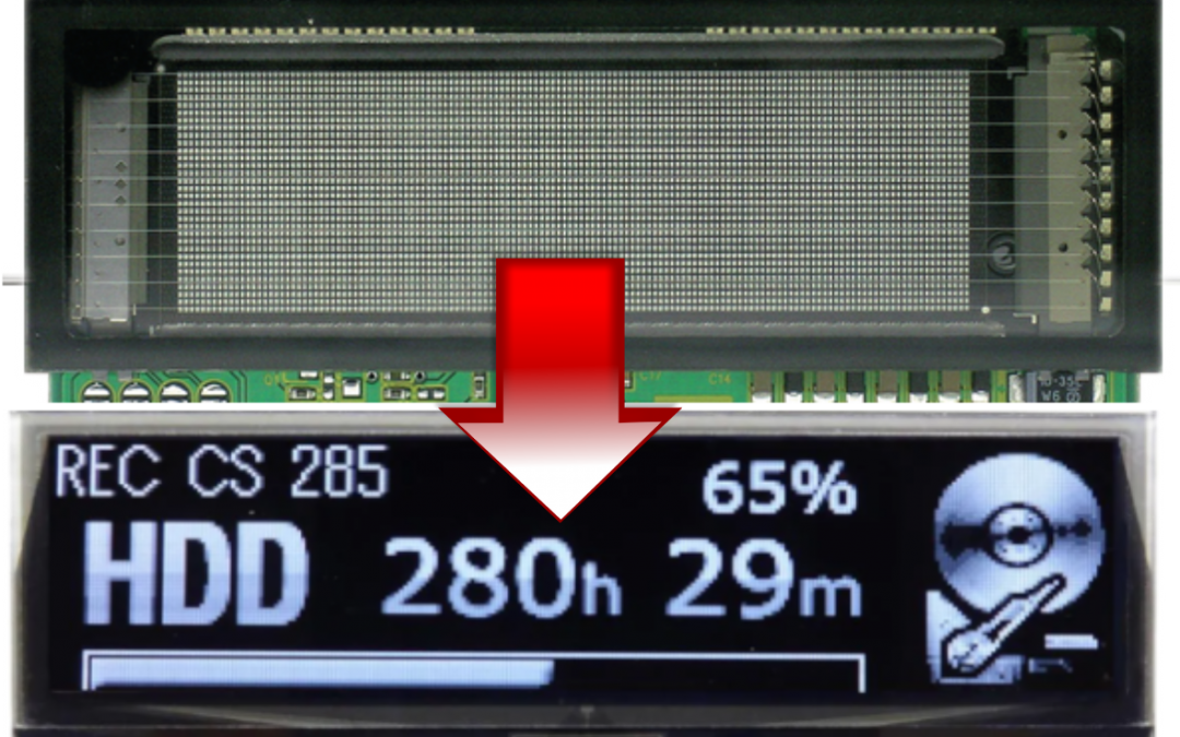
Now that Futaba has officially announced the EOL manufacturing of VFD displays, you may be considering an OLED display for its replacement. Here are a few things to consider.
Power requirements
VFDs typically require an operating voltage of up to 60Vdc, whereas the voltage for operating the OLEDs is between 13V-17V, so the module’s power circuit will need to be redesigned for these lower values.
Color
The VFD phosphor emits a green light, though can be filtered with colored filters to change to other colors, such as white. The OLED’s self-emitting luminance is designed to produce a near perfect white light without any filtering.
Physical Dimensions
Based on a comparable image area, the OLED will be thinner (typically less than 2mm), lighter weight (~ 3-8 gms) and smaller border (~ 2mm). The border is the edge from the image area to the outer edge of the glass, only about 2 mm.
Interface to the microcontroller
OLEDs offer similar interfaces to the VFD’s SPI.
Luminance
OLEDs appear to be roughly the same brightness, though will depend on the use of a CPL applied to the OLED.
Connection to the module
OLEDs are designed with an FPC and will be inserted into ZIF connector mounted to the PCBs. This allows for easy changed out if ever needed to be replaced. By contrast, VFD’s are soldered directly into the module PCB.
Full Graphic Capability
Since the OLEDs are fully graphic, if your image design needs to change, i.e. icon or font style, it is an easy software fix as opposed to retooling the a fixed icon VFD.
Storage and Operating Lifetimes
OLEDs can be comparable in the storage lifetime (years) and the operating lifetime (hours), though standard OLEDs may be able to be altered in their design and construction to extend both types lifetimes.
Need help?
Have more questions about converting from VFD to OLED? We would love to assist you. Please reach out to us via our Contact Us page.